Two-way Heat Dissipation PWM Four-wire Fan Temperature Control Governor 12V24V48V Temperature Speed Display Stop Alarm Board
Specifications:
Working voltage:DC8-60V (must be equal to the fan voltage, if you use 12V fan but supply 24V, it will burn the fan)
Working current:control board working current 35mA (12V) 22mA (24V)
Control ability:not limited by the fan current, but the current of the fan interface pin on the board should not exceed 3A. If you use a fan with a larger current, please connect the fan power cable directly to the main power supply!
Control output range:10%-100 (this is only the signal output range, the actual situation depends on the performance of the fan)
Temperature probe specification:NTC 10K B=3950
Temperature measurement:-9.9??C to 99.9??C error 2??C (1% probe within 70??C) 3??C (above 70??C)
Temperature control zone range:accelerated temperature 5-94??C, full speed temperature 10-99??C
Speed measurement:10-9990 rpm, if the speed is greater than this, it will always display 999, the resolution is 10 rpm, and the display unit is *10 rpm (the speed measurement is designed according to the common 2-pole signal fan, most fans are 2-pole signal)
Stopping alarm speed:below 375rpm
Circuit size:65mm*65mm*15mm, positioning hole center distance 56mm*56mm diameter 3.2mm
Weight:The main board + a pair of 1-meter wire cylindrical probes total about 40g, and the weight of the main board alone is about 23g.
Features:
1. DC8-60V wide working voltage range (here refers to the control board can work within this voltage range, in actual work, the controller power supply and the fan are together, so power supply must be in accordance with the fan power requirements, otherwise the fan will be damaged).
2. Dual-channel independent temperature control, which alternately displays the temperature of the two channels (-9.9??C to 70.1??C, error <1??C) and fan speed (resolution 10rpm, display up to 999*10rpm, greater than this speed display 999).
3. The low speed of the fan and the temperature control zone are all set by buttons, flexible control, wide setting range, and the program is saved after setting.
4. The stop alarm function of the switch can be set (the external AC buzzer beeps for a long time, and it is turned off by default).
Package Include:
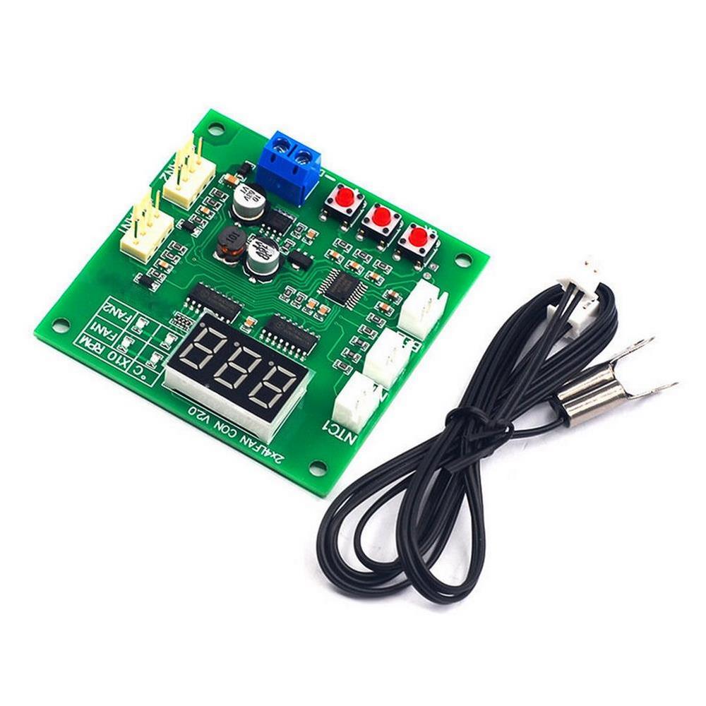
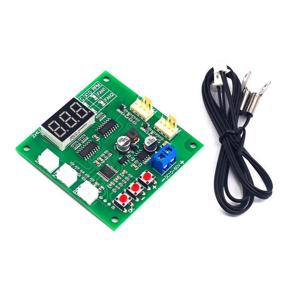
1??Module Board
1??Pair of 1-meter Cylindrical Probes
Wiring Instructions:
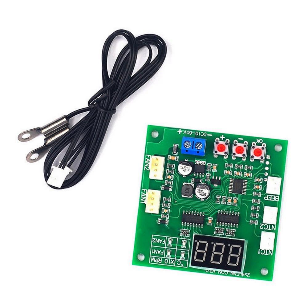
The blue screw terminal is connected to the main power supply (the power supply voltage is equal to the fan voltage used, and in the range of 8-60V), please pay attention not to connect the positive and negative polarities wrongly; ‘Channel 1’ and ‘Channel 2’ are connected to two 4P sockets Fan, the wire seequence is power supply negative, power supply positive, speed feedback, PWM control (please refer to the wiring diagram below for details); ‘Thermistor 1’ and ‘Thermistor 2’ are connected to NTC thermistors (the parameter is 10K B=3950) , to measure the temperature of the temperature control of the two-channel fan respectively; the ‘buzzer’ socket is connected to the AC buzzer, and when the stop alarm is turned on, the fan stop buzzer will beep for a long time.
Wiring Attention:
The allowable current of a single fan interface is 3A. If you need to control a fan with a higher current, please connect the fan power cable directly to the main power supply (the control capability of the controller has nothing to do with the fan current, just consider the current passing capacity of the power cable).
Show Instructions:
The control panel displays the value through the digital tube. The four LEDs on the right side of the digital tube indicate the meaning of the current value of the digital tube. The two LEDs on the first row represent the temperature and speed (x10rpm) of channel one respectively, and the two LEDs on the second row represent the channel two respectively. temperature and speed (x10rpm). Under normal working conditions, the four values will be displayed in turn in seequence. You can quickly switch the value manually by pressing the ‘+’ and ‘-‘ buttons at any time. After manual switching, it will stay at this value for a long time before entering the wheel display state. . The display of channel 2 can be shielded as required.
Setup Instructions:
1. Basic speed setting:The basic speed setting is used to adjust the fan speed before the temperature control starts, that is, the fan speed when it is lower than the acceleration temperature. The setting method is to press the ‘OK’ button in any running state, and at this time, the two LEDs in the horizontal direction of channel 1 light up at the same time, and the digital tube displays the current set value (between 10-100), through ‘+”- ‘ button to set the size, press and hold the button to modify it quickly and continuously, press the ‘OK’ button after setting, enter the basic speed setting of channel 2, use the same method to set, press the ‘OK’ button again to save and exit .
2. Temperature control temperature zone and stop alarm setting:Under normal operation, press and hold the ‘OK’ button until L** is displayed (** is the value), then release the button, and the two LEDs in the horizontal direction of channel one will light up at the same time, representing Now it is in the acceleration temperature setting state of channel 1, set this value through the ‘+’ and ‘-‘ buttons (range 5-94, unit Celsius); after setting, press the ‘OK’ button to enter the full speed temperature of channel 1 The setting state is displayed as ‘H**’, and the amount is set in the same way (range 10-99, unit Celsius); after setting, press the ‘OK’ button to enter the channel 1 stop alarm setting, ‘+”- ‘ button setting, ‘boF’ means turning off the stall alarm of this channel, and ‘bon’ means turning on the stall alarm of this channel; after setting, press the ‘OK’ button to enter the value setting of channel 2, the seequence and setting method are the same as Channel one is the same…. When the above settings are completed, press the ‘OK’ button to exit and save the parameters.
3. Channel 2 display shielding setting:When the control board is powered off, press and hold the ‘OK’ button and keep pressing it to power on, the digital tube will display ‘2on’ (open channel 2 display) or ‘2oF’ (block channel 2 display), release the ‘OK’ button, and set the switch shielding through the ‘+’ and ‘-‘ buttons. After setting, press the ‘OK’ button again to exit and enter the normal working state.
4. Normal and reverse timing mode switching:without connecting the fan, when the controller is not powered on, press and hold (note that it is to keep pressing) the ‘+’ and ‘-‘ buttons to supply power to the controller, and the controller enters the mode at this time Select the state, release the button, and click the ‘+’ or ‘-‘ button again to switch modes:display ‘F-1’ is the normal mode, display ‘F-2’ is the reverse timing mode, click ‘OK’ after modification Press the key to exit (automatically save when exiting) to set up.
Setting Note:
1. In the setting state of speed and temperature zone, if there is no operation after 15 seconds, it will automatically exit without saving the data.
2. When setting the temperature zone, the full-speed temperature of the same channel must be at least 5 degrees Celsius higher than the acceleration temperature. When a temperature value is set and this condition cannot be met, the controller will automatically adjust another temperature value to ensure that the difference is not low Under the condition of 5 degrees Celsius, this automatic adjustment is one-way, and if a callback is required, another temperature value needs to be manually adjusted.
3. The shielding display setting of channel 2 only affects the data display in the working state, the control and parameter settings of channel 2 are not affected, and it works normally.
Frequently Asked Questions:
1. No display when power on
The voltage is not suitable, the power supply is reversed – the controller can operate under DC8-60V input, please make sure the power supply voltage and polarity are correct (note that the power supply voltage should be consistent with the fan voltage).
2. The temperature display always shows -9.9??C, the actual temperature is not so low, or the displayed temperature is very different from the actual temperature.
The corresponding channel probe is not connected, the probe is in poor contact or damaged, and the probe parameters are incorrect – check the probe.
3. The fan does not turn
Wrong wiring seequence of the fan – please pay attention to the wiring seequence of the fan and the power cable.
There are some fans that will stop when the PWM value is lower than 20—-increase the manual speed control value.
4. The fan runs at full speed, cannot be controlled, and the speed is not displayed
The wiring order of the fan is wrong (the speed measurement line and the control line are reversed)—-exchange the control line and the speed measurement line of the fan (two lines except the power line).
The fan is unconventional PWM fan, counterffeit or shoddy, or the fan is faulty—-replace the fan
5. The fan can be controlled normally, but the speed is not displayed
The fan speed measuring line (the third line) is not connected reliably – check the wiring
The fan does not have a speed measurement signal or the fan speed measurement output port is faulty – replace another fan or ignore the speed display
6. The fan speed changes in reverse
The fan is an anti-sequential fan. Please refer to item 4 of the setting instructions to modify the controller’s operating mode.


Additional information
| Weight | 0.036 kg |
|---|






Reviews
There are no reviews yet.